8.6 KiB
8.6 KiB
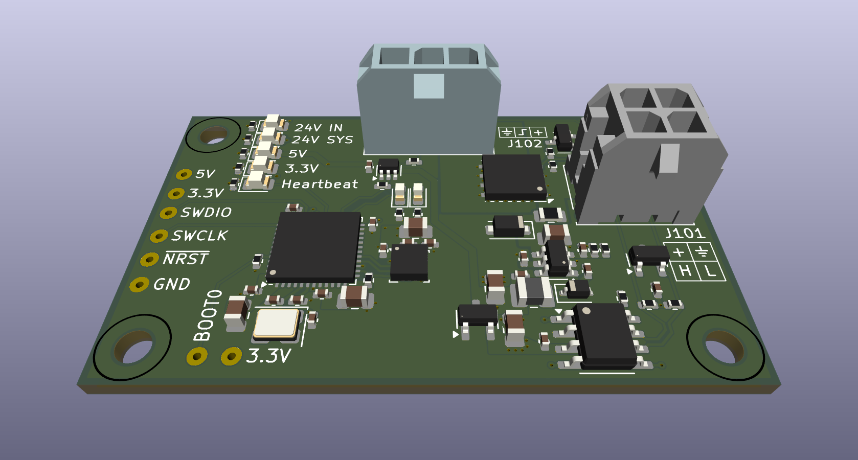
🔥 Laser CANbus Toolhead PCB
🇩🇪 Deutsche Version: README.de.md
A compact, robust toolhead board for Klipper-based laser engravers and cutters (CoreXY). This board integrates power supply, laser driver logic, CAN-Bus communication, and input shaping (ICM-20602) in the smallest possible space.
📚 Contents
- 🔥 Laser CANbus Toolhead PCB
✨ Features
🧠 Microcontroller
- MCU: STM32F072CBU6 (Cortex-M0, 48MHz, CAN-capable)
- Stability: 12MHz crystal for maximum CAN-Bus stability
- Firmware: Klipper-compatible
🔗 CAN-Bus Communication
- Transceiver: SN65HVD230 with ESD protection
- Termination: Split termination via solder jumper
- Slope Control: Switchable for EMI optimization
📊 Input Shaping
- Sensor: On-board ICM-20602 accelerometer/gyroscope (SPI)
- Purpose: Klipper resonance measurement for perfect print quality
- Advantage: Better availability and modern sensor technology
⚡ Laser Power Control
- Circuit: 24V / 6A High-Side Switch (CJAC70P06 P-MOSFET, 60V rated)
- Peak Current: 8A capability
- Soft-Start: Limits inrush current (Rise-time ~1.2ms)
- Safety: Hardware pull-down prevents unwanted activation
- Limitation: Max 6A limited by Micro Fit 3.0 connector with 0.75mm² wire
🎛️ Laser Signal Control
- PWM: 5V Level-shifted via 74AHCT1G125 buffer
- Quality: Clean edges, true hardware PWM via STM32 timer
- Compatibility: Common diode lasers
🔌 Power Supply
- Input: 24V with 250mA PTC fuse and SMF24A TVS diode
- 5V Rail: MP2459 Buck converter (up to 60V input tolerant)
- 3.3V Rail: XC6206 LDO for MCU and peripherals
🚨 Diagnostics & Monitoring
- Power LEDs: 24V In, 24V Sys, 5V, 3.3V
- Status LEDs: Laser Enable, Laser PWM, Heartbeat
📋 Klipper Configuration
Basic MCU Setup
[mcu toolhead]
canbus_uuid: <your-uuid>  # Find with "ls /dev/serial/by-id/*" or "~/klippy-env/bin/python ~/klipper/scripts/canbus_query.py can0"

[temperature_sensor toolhead_mcu]
sensor_type: temperature_mcu
sensor_mcu: toolhead
Input Shaping (ICM-20602)
[mpu9250]
cs_pin: toolhead:PA4
spi_bus: spi1
#axes_map: x,y,z  # Configure according to your printer orientation

[resonance_tester]
accel_chip: mpu9250
probe_points:
    150, 150, 20  # Adjust to your bed size
Laser Control
# Laser PWM Signal
[output_pin laser_pwm]
pin: toolhead:PB14
pwm: True
cycle_time: 0.001          # 1kHz PWM frequency
shutdown_value: 0          # Safety: laser off during emergency

# Laser Enable (optional)
[output_pin laser_enable]
pin: toolhead:PB15
value: 0
shutdown_value: 0

# Heartbeat LED (optional)
[output_pin heartbeat]
pin: toolhead:PA9
pwm: True
cycle_time: 1.0
🔌 Pinout & Connector Assignment
J101 - Power & CAN Input (Micro-Fit 3.0, 2x2, THT)
| Pin | Signal | Description |
|---|---|---|
| 1 | +24V | Main power input (High Current) |
| 2 | GND | Ground |
| 3 | CAN_H | CAN-Bus High Signal |
| 4 | CAN_L | CAN-Bus Low Signal |
J102 - Laser Output (Micro-Fit 3.0, 1x3, THT)
| Pin | Signal | Description |
|---|---|---|
| 1 | GND | Laser Ground |
| 2 | PWM | 5V PWM Signal (Level-Shifted) |
| 3 | +24V | Switched Laser Power (Soft-Start) |
Debug/Programming Header (Back Side)
| Pad | Pin | Signal | Function |
|---|---|---|---|
| 1 | - | 5V | 5V Supply (from Programmer) |
| 2 | - | 3.3V | VTref (Reference Voltage) |
| 3 | PA13 | SWDIO | Serial Wire Debug I/O |
| 4 | PA14 | SWCLK | Serial Wire Debug Clock |
| 5 | - | NRST | Reset Signal |
| 6 | - | GND | Ground |
💡 Bootloader Mode: To force the STM32 into DFU/Bootloader mode (e.g., for initial flash with Katapult), bridge the BOOT0 pad with 3.3V during power-on.
🔧 Installation & Setup
1. CAN-Bus Configuration
- Set CAN-Bus termination according to position in network
- Baud rate: 1 Mbit/s (Klipper standard)
2. Firmware Flash
- Put board into DFU mode (bridge BOOT0)
- Compile Klipper for STM32F072 with CAN support
- Flash firmware:
make flash FLASH_DEVICE=<dfu-device>
3. Find UUID
~/klippy-env/bin/python ~/klipper/scripts/canbus_query.py can0
⚠️ Safety Notes
- Laser Safety: Always wear protective eyewear
- Power Supply: Only operate with 24V DC
- Initial Setup: Slowly ramp up laser power
- Emergency: Hardware pull-down ensures safe state
🛠️ BOM (Bill of Materials) - Highlights
| Component | Value/Type | Function | Package | Order Code |
|---|---|---|---|---|
| U101 | STM32F072CBU6 | Main Microcontroller | UFQFPN-48 | STM32F072CBU6 |
| U102 | MP2459GJ-Z | Buck Converter 24V→5V | TSOT-23-8 | MP2459GJ-Z |
| U105 | SN65HVD230DR | CAN-Bus Transceiver | SOIC-8 | SN65HVD230DR |
| U106 | ICM-20602 | 6-Axis IMU (Accelerometer/Gyroscope) | LGA-16 | ICM-20602 |
| Q101 | CJAC70P06 | P-MOSFET (Laser Switch, 60V) | SOIC-8 | CJAC70P06 |
| D101 | SMF24A | TVS Diode (Overvoltage Protection) | DO-214AC | SMF24A |
| F101 | 1812L025 | PTC Fuse 250mA | 1812 | 1812L025 |
| Y101 | 12MHz | Crystal for CAN Stability | HC-49/S | 12MHz Crystal |
| J101/J102 | Micro-Fit 3.0 | THT Connectors | THT | Micro-Fit 3.0 THT |
🛠️ Technical Specifications
| Parameter | Value | Unit |
|---|---|---|
| Input Voltage | 24 ± 2 | V |
| Laser Current (max) | 4 | A |
| CAN Baud Rate | 1 | Mbit/s |
| PWM Frequency | 1 | kHz |
| Soft-Start Time | ~1.2 | ms |
| Operating Temperature | -10 to +70 | °C |
| Dimensions | TBD | mm |
📝 Changelog
Rev. 1
- Transistor Upgrade: Replaced MOSFET with CJAC70P06 (60V voltage rating)
- Sensor Upgrade: Changed from ADXL345 to ICM-20602 (better availability, modern 6-axis IMU)
- Connector Change: Micro Fit 3.0 connectors changed from SMD to THT mounting
- Silkscreen Enhancement: Added connector pin assignments to silkscreen for easier assembly
- Layout Improvements: Cleaned up component placement and optimized routing
- Documentation: Updated overview image to reflect current design
- BOM Update: Added component order numbers and updated production data
- Production Files: Updated assembly and production files with current components
Rev. 0 (Initial Release)
- Initial PCB design with STM32F072CBU6 microcontroller
- CAN-Bus communication with SN65HVD230 transceiver
- 24V/4A laser power control with AO4407A MOSFET
- ADXL345 accelerometer for input shaping
- MP2459 buck converter for power supply